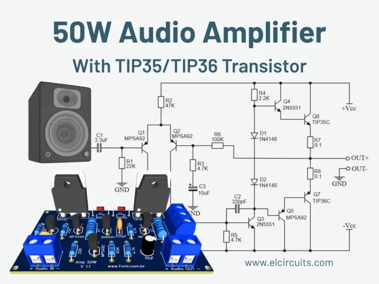
Tag Archives: Power Amplifier

TDA2030 Chip Amp 200 Watts Audio Power Amplifier

TDA2030 Chip Amp 200 Watts Audio Power Amplifier

TDA2030 Chip Amp 200 Watts Audio Power Amplifier

The TDA2030 amp can deliver 200 watts audio power amplifier low cost, high power audio output up to 200 watts on a 2-4 ohm impedance. This 200 amp watt high power amplifier audio around the TDA2030 audio amplifier IC that normally built an up to 14 watts on a 4 ohm load, but if used in a bridge mode, if we can power transistors expensive 200-watt audio high power amplifier can be generated.

LM4651 and LM4652 125 Watt Class-D Ultra Low Noise Audio Power Amplifier

LM4651 and LM4652 125 Watt Class-D Ultra Low Noise Audio Power Amplifier

LM4651 and LM4652 125 Watt Class-D Ultra Low Noise Audio Power Amplifier

National Semiconductor LM4651 LM4652 new design category for the WD 125 ultra low power amplifier circuit as shown below. The amplifier THD = 1% of the output power of 125 W load impedance RL = 4 ?, the input signal Vin (rms) for the highest V-3, the bandwidth of the input signal of 150 Hz ~ 10, ambient temperature is 50 ?, voltage of ± 20V.

400 Watts MOMSFET Power Amplifier IRFP448

400 Watts MOMSFET Power Amplifier IRFP448

400 Watts MOMSFET Power Amplifier IRFP448

400watt power amplifier IRFP448
400W power amplifier circuit IRFP448
Amplifier circuit today we would like musical Pro amplifier MOSFET 400 W amplifier is on my kilowatts, which is the same design and main PCB. The only real difference is the character of the process output device. We are designing the use IRFP448 MOSFET amplifier, while the 14 O / P process.

Build 35 Watts Tube Power Amplifier with EL34

35 Watts Tube Power Amplifier with EL34 Schematic

35 Watts Tube Power Amplifier with EL34 Schematic

It’s a classic designing of final amplifier 35 W, with two EL34 in push-pull, from the Siemens and Halske, with year of designing 24/3/1953 and code SV410/1. The amplifier it worked from 1954 until 1989, whenever it came also out except operation, with mean of operation 15 hours per day.

It did not present particular damage beyond the replacement of tubes, resistances and capacitors, result of natural deterioration. A essential change became with the replacement of restoring provision from tube, with diodes. The alone problem that will exist, for those who they try his manufacture, will be the transformer of expense, (it is in effect for all the tube manufactures), one and code that exists it will help.

200 Watt Power Amplifier STK4050 II

200 Watt Power Amplifier STK4050 II Schematic

200 Watt Power Amplifier STK4050 II Schematic

200 watt Power Amplifier STK4050 II
Features STK4050 II

Compact package for thin-type audio sets
Member of pin-compatible series with outputs of 20 to
200W
Easy heatsink design to disperse heat generated in thintype
stereo sets
Constant-current circuit to reduce supply switch-on and
switch-off shock noise
External supply switch-on and switch-off shock noise
muting, load short-circuit protection, thermal shutdown
and other circuits can be tailored-designed

TDA8560Q PHILIPS Stereo BTL Car Power Amplifier 2x 40 Watts

TDA8560Q PHILIPS Stereo BTL Car Power Amplifier 2x 40 Watts

TDA8560Q PHILIPS Stereo BTL Car Power Amplifier 2x 40 Watts

TDA8560Q PHILIPS – more powerful analog of the well-known TDA1557Q. Analogue is also TDA8563Q.

IC TDA 8560, being a complete analog of chip TDA1557Q, in fact – a brand new amp. Developers TDA 8560 “only” umoschnili output stage (taking as a basis TDA 1557), “teach” the amplifier to 2 ohms *. What gives?

Toshiba A1943 C5200 Sweet Sound Quality Audio Power Amplifier

Toshiba A1943 C5200 Sweet Sound Quality Audio Power Amplifier

Toshiba A1943 C5200 Sweet Sound Quality Audio Power Amplifier

The audio power amplifier input stage and the voltage amplifier stage differential circuit using two asymmetric structure and enlarge good linearity, wide frequency response, temperature drift and power fluctuations suppress strong, sweet sound, full of flavor.

A circuit Introduction ??The figure below shows the main amplifier amplifier circuit. VT2, VT3 constitute the input differential circuit, VT1, LED1, R3, R8 and C2 form the constant current source circuit of the input differential circuit. LED1 light of its positive and negative terminals of the voltage difference between a 2V 1.8V constant noise is less than the Zener diode, commonly used in the amplifier circuit. Their positive and negative ends around 1,9 V voltage difference acting on the VT1 emitter junction circuit, so that the VT1 shot a set constant current (1.9V-0.6V) / 680? ? 1.9mA. VT2, VT3 differential input circuit parameters completely symmetric case, flows through the VT2, VT3 shot a set current is 1.9mA half 0.95mA. RP1 change VT2, VT3 emitter feedback resistor, so that VT2, VT3 static operating point symmetrical changes, and ultimately change the midpoint of the output stage of the DC-bit.

LA4445 IC Audio Power Amplifier with Tone Control

LA4445 IC Audio Power Amplifier with Tone Control Circuit Diagram

LA4445 IC Audio Power Amplifier with Tone Control Circuit Diagram

The audio power amplifier is an important component part of the audio system, an audio signal to obtain a sufficient driving power through its enlarged after completion of the reproduction of the sound signal fed to the speaker. The stereo power amplifier as the core is based on the the Sanyo design of integrated circuit LA4445.

LM3875 80W Audio Power Amplifier Bridge Mode Schematic

LM3875 80W Audio Power Amplifier Bridge Mode Schematic

LM3875 80W Audio Power Amplifier Bridge Mode Schematic

A very simple high efficiency 80W audio power amplifier project can be designed using the LM3875 power audio IC . LM3875 is a high-performance audio power amplifier capable of delivering 56W of continuous average power to an 8? load with 0.1% THD+N from 20Hz to 20kHz.

By connecting two LM39875 audio IC in bridge mode this audio power amplifier will deliver 80 watt of output power into an 8 Ohm load. The LM3875 IC devices should be suitably heatsink.

UCD Project Class-D Power Amplifier Subwoofer H-Bridge

UCD Project Class-D Power Amplifier Subwoofer H-Bridge

UCD Project Class-D Power Amplifier Subwoofer H-Bridge

Collecting information aboit UcD class d amp for subwoofer and need your help,
because it is a new area for me.

Here it is the requirements for the project:

1. It is UcD type class d amp.
2. uses full h-bridge – 2 x IR2110 + 4 x IRFB4227 + 2 x T200-2 as output filter.
3. Single supply +50 V !! ( transformer is allready in my hand !! )