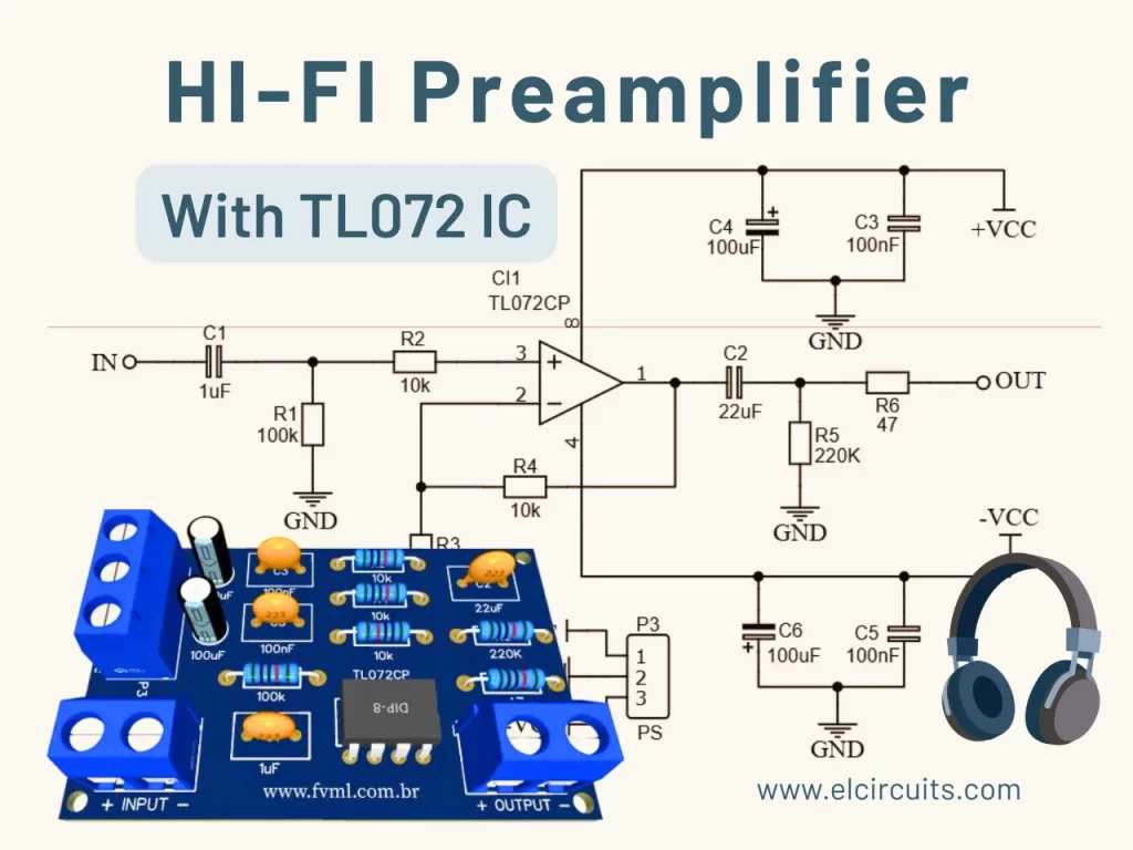
Friday, October 17, 2025

Complete AWG Enameled Wire Table: Your Definitive Guide

Complete AWG Enameled Wire Table - elcircuits.com
Complete AWG Enameled Wire Table

🌐 You can read this article in: Português | Español

"If you've ever spent hours choosing the wrong wire for your project, this guide will save you time, money, and frustration. Let's decipher the mysterious AWG table together!"

Why is the AWG Table Essential for Your Project?

Hello, fellow designers, students, and electronics enthusiasts! If you've ever faced the cruel question: "What wire gauge to use in this winding?", know that you're not alone. The standard AWG enameled wire table is your new best friend - and today I'll explain not only how to read it, but how to extract information from it that can make the difference between a project that works and one that goes up in smoke!

The AWG (American Wire Gauge) standard is the most widely used wire diameter measurement system in the world. Understanding this table is fundamental for transformer, coil, motor projects, and any application that requires precise windings. Errors in wire selection can cause overheating, efficiency losses, or even catastrophic failures.

💡 Teacher's Tip: The Secret is in the AWG

"The higher the AWG number, the smaller the wire diameter. It seems counterintuitive at first, but you'll get the hang of it. AWG 10 is a thick wire, while AWG 30 is as thin as hair!"

Understanding Your AWG Table: Decoding Each Column

Let's analyze each column of the table calmly. Don't worry if it seems complicated at first - I'll explain everything as if we were in a practical class!

1. AWG Gauge: Your Starting Point

The first column shows the AWG number. This is your main reference. In our example, we have from AWG 000 (three zeros, a very thick wire) to AWG 40 (an extremely thin wire).

2. Wire Diameter: How Thick Is It?

This column shows the wire diameter in millimeters. It's essential for calculating the necessary space in the core of your winding. Note that the diameter decreases as the AWG number increases - this is where many beginners get confused!

3. Cross-Sectional Area: Why Does This Matter?

The cross-sectional area (in mm²) determines the current-carrying capacity of the wire. The larger the area, the greater the current that can pass without overheating. This information is critical for projects that require high efficiency.

How to Use This Table in Your Projects: Practical Applications

Practical Example: Designing a Coil for a Switching Power Supply

Let's suppose you need to design a coil for a switching power supply that works with 5A of current. Consulting our table:

  • For 5A, you'll need a wire with a minimum cross-sectional area of approximately 0.75mm² (general rule: 6-7A/mm² for continuous applications)
  • Consulting the table, AWG 18 has 0.823mm² - perfect for your application!
  • Also check the wire diameter (1.024mm) to ensure it will fit in the available space for winding

📌 Professional Tip: When designing transformers or inductors, always consider the "fill factor" - the area occupied by the wires will be about 70% of the available area due to spaces between the wires. Never fill 100% of the space!

Common Mistakes (and How to Avoid Them)

❌ Mistake #1: Ignoring Wire Resistance

The wire resistance (shown in the table in Ω/km) can cause significant losses in high-current projects. Always calculate the expected voltage drop!

❌ Mistake #2: Forgetting the Enamel Thickness

The total diameter of enameled wire is greater than the diameter of pure copper. This directly affects how many turns will fit in your core!

Complete Quick Reference Table

To facilitate your daily work, I've organized the most used data in a simplified table. Use it as a quick reference in your projects:

AWG Wire Diameter (mm) Area (mm²) Resistance (Ω/km) Max Current (A) Diameter with Enamel (mm) Weight (kg/km) Turns/cm² Max Frequency (kHz)
0000 (4/0) 11.684 107.22 0.1608 195 11.94 846.6 0.71 0.065
000 (3/0) 10.405 85.03 0.2028 165 10.66 671.9 0.89 0.073
00 (2/0) 9.266 67.43 0.2557 145 9.52 533.0 1.00 0.082
0 (1/0) 8.251 53.49 0.3224 125 8.51 422.4 1.13 0.092
1 7.348 42.41 0.4066 110 7.60 335.1 1.27 0.103
2 6.544 33.63 0.5127 95 6.80 265.9 1.43 0.116
3 5.827 26.67 0.6465 85 6.08 210.9 1.61 0.130
4 5.189 21.15 0.8152 70 5.44 167.3 1.81 0.146
5 4.621 16.77 1.028 60 4.88 132.8 2.03 0.164
6 4.115 13.30 1.296 55 4.37 105.2 2.28 0.184
7 3.665 10.55 1.634 45 3.92 83.41 2.56 0.207
8 3.264 8.366 2.061 40 3.52 66.19 2.88 0.232
9 2.906 6.634 2.599 30 3.16 52.52 3.24 0.260
10 2.588 5.261 3.277 30 2.84 41.62 3.64 0.291
11 2.305 4.174 4.132 25 2.56 33.00 4.10 0.327
12 2.053 3.309 5.211 20 2.31 26.18 4.60 0.367
13 1.828 2.624 6.574 15 2.08 20.77 5.17 0.412
14 1.628 2.081 8.286 15 1.88 16.47 5.82 0.462
15 1.450 1.650 10.45 10 1.71 13.05 6.56 0.519
16 1.291 1.309 13.17 10 1.55 10.35 7.38 0.583
17 1.150 1.038 16.61 8 1.41 8.214 8.30 0.655
18 1.024 0.823 21.35 5 1.28 6.519 9.32 0.735
19 0.912 0.653 26.47 5 1.17 5.167 10.47 0.824
20 0.812 0.518 33.31 3 1.07 4.100 11.77 0.923
21 0.723 0.410 42.00 3 0.98 3.249 13.22 1.034
22 0.644 0.326 53.15 2 0.90 2.578 14.84 1.160
23 0.573 0.258 66.79 2 0.83 2.043 16.66 1.302
24 0.511 0.205 84.21 1 0.77 1.620 18.70 1.460
25 0.455 0.162 106.2 1 0.71 1.283 20.97 1.638
26 0.405 0.129 133.9 0.8 0.66 1.016 23.51 1.838
27 0.361 0.102 168.9 0.6 0.62 0.805 26.35 2.063
28 0.321 0.0810 212.6 0.5 0.58 0.638 29.53 2.316
29 0.286 0.0642 267.9 0.4 0.54 0.506 33.10 2.599
30 0.255 0.0509 337.8 0.3 0.51 0.401 37.12 2.917
31 0.227 0.0404 425.0 0.25 0.48 0.318 41.64 3.272
32 0.202 0.0320 536.4 0.20 0.45 0.252 46.74 3.670
33 0.180 0.0254 676.3 0.15 0.43 0.200 52.50 4.117
34 0.160 0.0201 852.4 0.12 0.41 0.158 58.99 4.619
35 0.143 0.0160 1074 0.10 0.40 0.126 66.29 5.183
36 0.127 0.0127 1355 0.08 0.39 0.100 74.48 5.815
37 0.113 0.0100 1709 0.06 0.38 0.079 83.69 6.524
38 0.101 0.0080 2152 0.05 0.37 0.063 94.06 7.317
39 0.089 0.0063 2713 0.04 0.36 0.050 105.8 8.203
40 0.080 0.0050 3417 0.03 0.35 0.039 119.0 9.191

🔍 Want the complete high-resolution table?

Download our practical guide with the complete AWG table + winding calculator for free!

Frequently Asked Questions about AWG Enameled Wire (FAQ)

1° What is the difference between enameled wire and regular wire?

Enameled wire has an ultra-thin insulating layer of varnish (enamel), while regular wire uses a thicker plastic sheath. Enameled wire is essential for windings where space is limited, as it allows wires to touch each other without causing short circuits, maximizing the number of turns in the same space.

2° How to choose the correct AWG for my transformer?

First calculate the maximum current that will pass through the winding. Use the practical rule of 3-5A/mm² for transformers (depending on cooling). Consult the table to find the AWG with adequate cross-sectional area. Then, check if the total diameter (with enamel) allows all turns to fit in the available core.

3° Can I replace an AWG 18 wire with two AWG 21 wires in parallel?

Yes, technically yes - two AWG 21 wires have a combined area close to an AWG 18. However, in practice, thinner wires have higher resistance due to the skin effect at high frequencies. For low-frequency applications (like 60Hz mains transformers), it might work, but for switching power supplies, prefer the single thicker wire.

4° What is the maximum operating temperature of enameled wire?

It depends on the type of enamel. The most common are class A (105°C), class B (130°C), class F (155°C) and class H (180°C). Always choose a wire with a thermal class above the maximum temperature expected in your project, with a safety margin of at least 20°C.

Original article published on FVML (Portuguese) – March 12, 2019

👋 I hope you enjoyed it!!!

If you have any questions, suggestions or corrections, please leave them in the comments and we will answer them soon.

🙏 Subscribe to our blog!!! Click here - elcircuits.com!!!

My Best Regards!!!

Build a 50W RMS Audio Amplifier with Mosfet | Complete DIY Guide

Simple 50W RMS Audio Amplifier with Mosfet - elcircuits
Simple 50W RMS Audio Amplifier with Mosfet

🌐 You can read this article in: Português | Español

Hello, electronics enthusiasts!

Today we're going to dive into the fascinating world of audio amplifiers! Get ready to build a simple yet excellent quality Audio Amplifier with 2 Mosfet output transistors that will surprise you with its 50W RMS on an 8 ohm speaker.

This project is perfect both for beginners who want to improve their skills and for hobbyists looking for an efficient amplifier with good sound quality.

🔬 Amplifier Technical Specifications

Output Power 50W RMS
Load Impedance 8 ohms
Supply Voltage +/- 35V DC
Maximum Current 2A (mono) / 4A (stereo)
Output Configuration Complementary push-pull with Mosfets

👨‍🔧 How Does This 50W RMS Amplifier Work?

Before we get our hands dirty, let's understand how this circuit works. The amplifier is divided into three main stages, each with a specific function to ensure clear and powerful sound reproduction.

1️⃣ Input Stage: Differential Amplifier

The first stage of the amplifier is a differential amplifier based on the PNP transistors BC556, Q1 and Q2. This stage is responsible for receiving the low-amplitude audio signal and preparing it for the following stages.

The capacitor C2 functions as an input DC decoupler, ensuring that only the audio signal passes through. The resistor R1 limits the input current, protecting the circuit, and the capacitor C1 diverts unwanted high frequencies, functioning as a simple low-pass filter.

2️⃣ Driver Stage: The Heart of the Amplifier

The second stage is the drive stage composed of the transistors Q3, BC546, and the transistor Q4. This section functions as a voltage amplifier, increasing the signal received from the input stage and preparing it for the output stage. Additionally, this stage aims to regulate the bias of the output transistors, ensuring they operate in their linear region and minimizing distortion.

3️⃣ Output Stage: Power and Efficiency with Mosfets

The output stage is a complementary push-pull stage based on the MOSFETs IRF530 and IRF9530. This configuration is ideal for power amplifiers, as one MOSFET conducts the positive half of the signal while the other conducts the negative half, resulting in high efficiency and low distortion.

The output is coupled to the speaker using the inductor L1, which helps to isolate the speaker from any DC component that might be present in the output signal.

💡 Expert Tip

If you don't have access to any of these specific transistors, don't worry! We provide on our website a tool called:

Equivalent BJT Transistor by Data Cross-Reference

With this tool, you ensure the correct functioning of the circuit, even using components different from those suggested here.

📌 Additional Components: Stability and Quality

The network composed of R15 and C5 is intended for noise reduction, functioning as a Zobel filter to stabilize the load and prevent high-frequency oscillations. The capacitors C6 and C7 are power supply filters, essential for eliminating ripple and ensuring a clean power supply for the circuit.

The variable resistor R6 is a crucial component intended to adjust the quiescent current of the bias transistor, allowing optimization of the MOSFETs' operating point for lower distortion.

🔌 50 Watt Amplifier Circuit Diagram

In Figure 2 below, we have the schematic diagram of the circuit. Despite being a circuit with few components, we must pay special attention during assembly, as we are working with at least 6 transistors, diodes, and electrolytic capacitors with defined polarities.

⚠️ Attention: If any component is inverted, we can cause component burnout or even small explosions, in the case of capacitors. Always check the polarity before soldering!

Schematic Diagram 50W RMS Audio Amplifier with Mosfet - elcircuits
Fig 2 - Schematic Diagram 50W RMS Audio Amplifier with Mosfet

💡 Tips for Circuit Assembly

We don't currently have a printed circuit board, so when building your amplifier, assemble it on a good quality PCB. Here are some important tips:

  • Use a good quality printed circuit board with thick copper to support the necessary current
  • Keep audio signal traces as short as possible to reduce noise
  • Separate power traces from signal traces to avoid interference
  • Use good quality solder and check all connections before powering the circuit

🧾 Complete Bill of Materials

To facilitate your assembly, we've organized all necessary components in a clear and detailed table. Note everything before starting your project!

Component Reference Specifications Color Code / Notes
🔌 TRANSISTORS
PNP Transistor Q1, Q2 BC556 -
NPN Transistor Q3, Q4 BC546 -
N-Channel MOSFET Q5 IRF530 -
P-Channel MOSFET Q6 IRF9530 -
⚡ DIODES
Rectifier Diode D1 1N4002 (1N4001, 04, 05, 07)
🔋 CAPACITORS
Ceramic/Polyester C1 220pF -
Electrolytic C2, C3 47µF - 35V -
Electrolytic C4 100µF - 35V -
Ceramic/Polyester C5 68nF -
Electrolytic C6, C7 100µF - 50V -
🔧 RESISTORS
Resistor R1, R12 4.7KΩ yellow, violet, red, gold
Resistor R2, R5 47KΩ yellow, violet, orange, gold
Resistor R3 15KΩ brown, green, orange, gold
Resistor R4 1.2KΩ brown, red, red, gold
Resistor R6 1KΩ brown, black, red, gold
Resistor R7 820Ω gray, red, brown, gold
Resistor R8 10KΩ brown, black, orange, gold
Resistor R9 680Ω blue, gray, brown, gold
Resistor R10, R11 2.7KΩ red, violet, red, gold
Resistor R13 560Ω green, blue, brown, gold
Resistor R14 2.2KΩ red, red, red, gold
Resistor (2W) R15 10Ω / 2W brown, black, black, gold
🎛️ ADDITIONAL COMPONENTS
Trimpot RP1 1KΩ -
Connector (2 pins) P1, P2 WJ2EDGVC-5.08-2P -
Connector (3 pins) P3 WJ2EDGVC-5.08-3P -
Coil L1 5µH - 10 turns 18AWG 3/8" (1cm) core
Miscellaneous - Heatsink, Wires, Solder -

⚡ Adequate Power Supply

To ensure maximum performance of your amplifier, it's crucial to use an adequate power supply. The required power supply is of the symmetric type +/- 35V DC, with a current of at least 2 Amperes.

This voltage and current are essential for the amplifier to deliver the promised 50W RMS with low distortion.

💡 Tip for Stereo Configuration

For those who want to build a stereo amplifier, just build two identical circuits and double the power supply current to 4 Amperes. Remember that each channel will need its own set of components and heat sink!

🌀 Construction of Coil L1

For the coil L1, wind 12 turns of enameled copper wire 18AWG with a diameter of 3/8" or 1cm without a physical core. This coil is crucial to isolate the speaker from any DC component and improve the frequency response of the amplifier.

🔵 Selection of Capacitors

The electrolytic capacitors C6 and C7, which act as power supply filters, should have minimum voltages of 50V to ensure safety and durability. The other electrolytics can be 25 or 35V, as long as they respect the specified capacitance values.

📏 Essential Heat Sink

An adequate Heat Sink is necessary for the MOSFETs. We recommend a heatsink with medium dimensions of 22x12x12cm with sufficient dissipation area to ensure that the transistors operate at safe temperatures, even at higher volumes. Remember to use thermal paste between the MOSFETs and the heatsink for better heat transfer!

⚠️ Important Warning

Pay attention to the speaker, as the output of this amplifier is 50W RMS. Make sure your speaker can handle this power to avoid damage. Speakers with lower power can be damaged at higher volumes!

🎵 Test and Adjustment

After assembling the circuit, before connecting the speaker, adjust the trimpot RP1 to approximately the middle of its course. Connect a multimeter in series with the power supply and check if the quiescent current is between 50-100mA. Adjust RP1 as necessary to obtain this value.

🤔 Possible Problems and Solutions

If you encounter problems during the assembly or operation of the amplifier, here are some solutions to the most common problems:

Problem Possible Cause Solution
No sound at output Incorrect connections or damaged components Check all connections and test the components
Distorted sound Incorrect bias or insufficient power supply Adjust RP1 and check the power supply
MOSFETs overheating Inadequate heatsink or excessive bias Improve the heatsink or reduce the RP1 adjustment
High-frequency noise Instability or interference Check capacitor C5 and the board layout

🛠️ Optional Improvements

If you want to take your amplifier to the next level, here are some improvements that can be implemented:

  • Short-circuit protection: Adding a protection circuit can prevent damage to the MOSFETs in case of a short at the output.
  • Enhanced power supply filter: Larger capacitors or addition of inductors in the power supply can further reduce noise.
  • Mute circuit: Implementing a mute circuit can prevent noise when turning the amplifier on/off.
  • Power indicator: Adding LEDs or a VU meter can give a more professional look to your project.

❓ Frequently Asked Questions (FAQ)

1° What is the real power of this amplifier?

This amplifier delivers 50W RMS on an 8-ohm speaker, when powered with a symmetric supply of +/- 35V. This is real power (RMS), not peak power or PMPO.

2° Can I use other MOSFET transistors instead of IRF530 and IRF9530?",

Yes, you can use other MOSFETs with similar characteristics. We recommend MOSFETs with operating voltage of at least 60V and maximum current of 17A or more. Some possible substitutes are IRF540/IRF9540 or IRFZ44/IRF9Z34.

3° Does this amplifier need a symmetric power supply?

Yes, this circuit was designed to work with a symmetric power supply of +/- 35V. Trying to use a single supply will result in incorrect operation and possibly damage to the components.

4° How should I adjust the trimpot RP1?

The trimpot RP1 adjusts the quiescent current (bias) of the MOSFETs. Start with it in the central position and measure the quiescent current with a multimeter. The ideal is between 50-100mA. Adjust slowly until you obtain this value. A very low current can cause distortion, while a very high one can overheat the transistors.

5° Can I use this amplifier for subwoofers?

Yes, this amplifier works well for subwoofers, but you may need to adjust the value of capacitor C1 to decrease the cutoff frequency of the input high-pass filter. A value between 470pF and 1nF would be more suitable for subwoofer applications.

Good luck with your project!

📸 Share Your Project!

We would love to see your finished amplifier! Share photos of your project on social media tagging our profile. The best projects will be featured in our next article!

Original article published on FVML (Portuguese) – August 12, 2019

👋 I hope you enjoyed it!!!

If you have any questions, suggestions or corrections, please leave them in the comments and we will answer them soon.

🙏 Subscribe to our blog!!! Click here - elcircuits.com!!!

My Best Regards!!!